Industrial 3D Printing · FDM, SLA & SLS
Digital Models.Physical Parts.
Industrial additive manufacturing for rapid prototypes, complex geometry, fixtures, and low-volume functional parts.
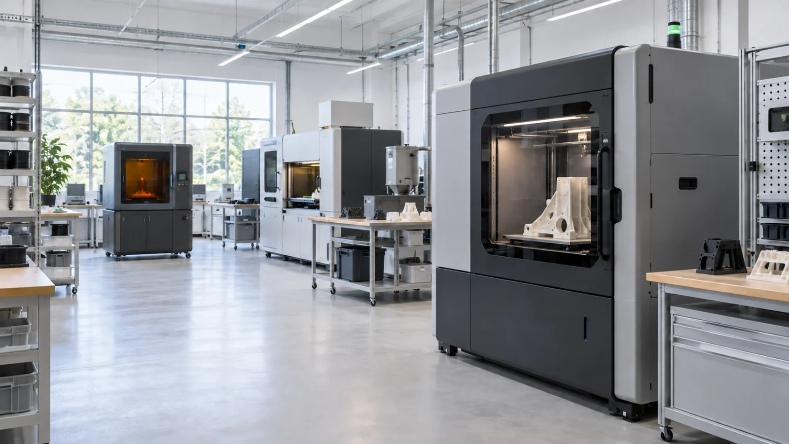
Start with your CAD file
Upload. Configure. Get your price.
STL, 3MF or STEP
Online quoting coming soon
What Is 3D Printing?
3D printing, also called additive manufacturing, converts a digital model into a physical part by building material layer by layer.
The process is well suited to complex internal geometry, lightweight structures, and rapid design iteration. Common outputs include prototypes, jigs, fixtures, visual models, and low-volume functional parts.
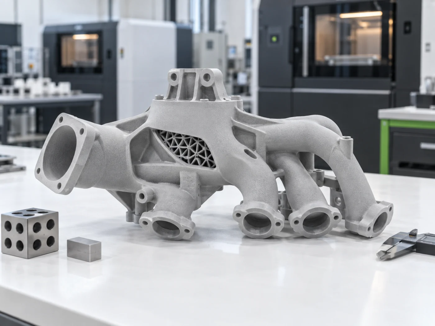
PartGo supports FDM, SLA, and SLS process categories. The right technology depends on geometry, material behavior, surface finish, strength, and application requirements.
How the 3D Printing Process Works
A typical order moves from the uploaded model through setup, printing, post-processing, and inspection.
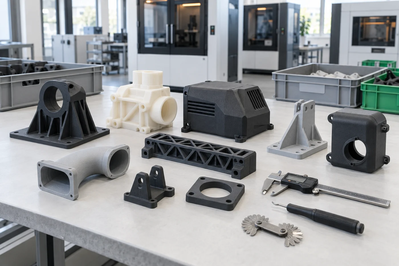
Prepare the 3D Model
Upload an STL or STEP model for geometry and manufacturability review.
Slicing & Setup
The model is oriented and sliced into layers, with supports and build parameters defined.
Production
The part is built layer by layer using the selected FDM, SLA, or SLS process.
Post-Processing
Supports and excess material are removed, followed by the specified finishing operations.
3D Printing Technologies
Compare FDM, SLA, and SLS to identify the process that best fits your part and application.
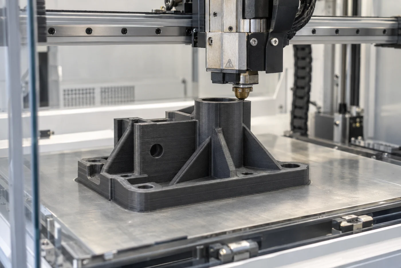
Thermoplastic filament is melted and deposited through a nozzle layer by layer. FDM is widely used for functional prototypes, jigs, fixtures, and low-volume parts.
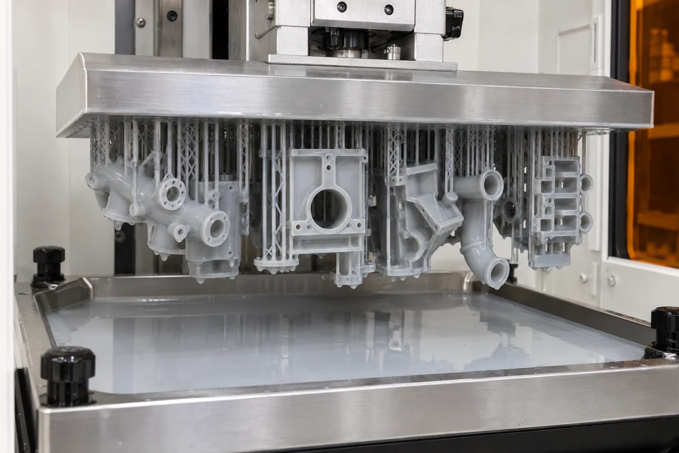
A UV light source cures liquid photopolymer resin layer by layer. SLA is selected for fine details, smooth surfaces, visual prototypes, patterns, and models.
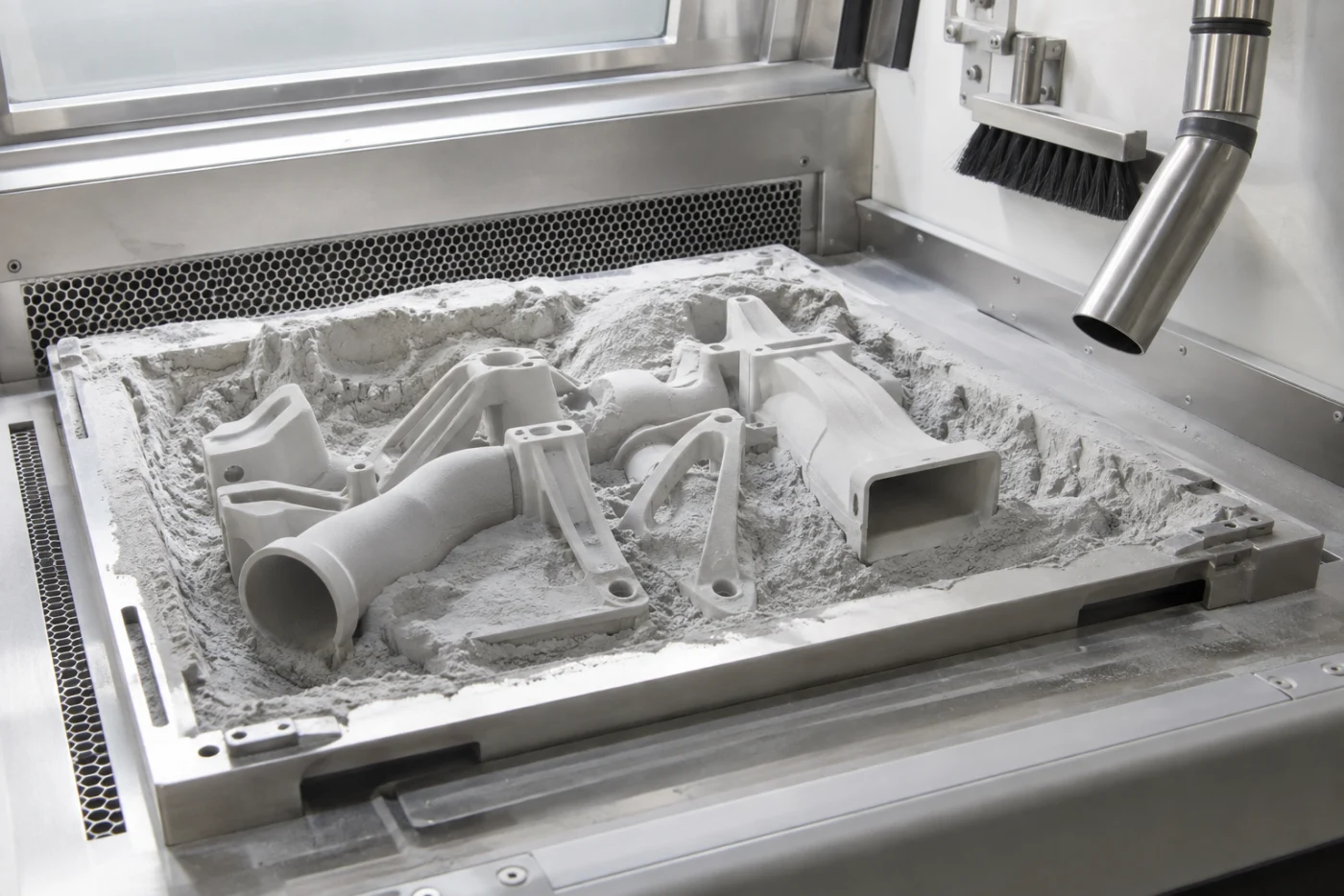
A laser selectively fuses polymer powder. The powder bed supports the part, enabling complex geometry without dedicated support structures.
3D Printing Capabilities and Tolerances
Representative capabilities are shown below. Final limits depend on process, material, geometry, and build orientation.
3D Printing Tolerance Guide
Tolerance varies by process, material, feature size, and orientation. Use these values as general design guidance.
| Operation | Tolerance | Description | Rating |
|---|---|---|---|
| FDM — XY plane | ±0.20 mm | In-plane dimensional tolerance | Standard |
| FDM — Z axis | ±0.30 mm | Dimension along the layer direction | Standard |
| SLA — general | ±0.10 mm | General tolerance across axes | Precision |
| SLA — detail | 0.3 mm | Minimum positive feature size | Precision |
| SLS — general | ±0.15 mm | General PA12 powder-bed tolerance | Good |
| SLS — hole diameter | ±0.10 mm | Minimum hole diameter depends on orientation | Good |
| Minimum wall thickness | 0.8–1.2 mm | Varies by process and material | General |
Design Tips for 3D Printing
Use these guidelines to improve print quality, manufacturability, and part performance.
Avoid Long Unsupported Bridges
Unsupported horizontal spans can sag in FDM. Reduce bridge length, adjust orientation, or provide support-friendly geometry.
Use Adequate Wall Thickness
Minimum wall thickness varies by process, material, geometry, and orientation. Thin walls can distort or break.
Avoid Extremely Fine Raised Details
Small text and raised features may not resolve cleanly. Match feature size to the selected process.
Design with Build Orientation in Mind
Orientation affects support requirements, surface finish, dimensional behavior, and strength between layers.
Avoid Large Unreinforced Flat Surfaces
Large flat areas can warp. Add ribs, curvature, or other stabilizing geometry where appropriate.
Allow Clearance Between Mating Parts
Provide process-appropriate clearance for assemblies and add powder-removal openings to enclosed SLS geometry.
File Formats for 3D Printing
A clean, high-resolution STL or a valid STEP solid model provides the best starting point.
STL / 3MF
The standard mesh format for 3D printing. Export at a sufficiently high resolution to preserve curved surfaces and small features.
STEP / IGES
Submit a solid CAD model when you want to preserve exact geometry before the model is converted to a printable mesh.
Export STL files using a fine or high mesh resolution. A coarse mesh creates visible facets on curved surfaces.
Frequently asked
questions
Review common questions about 3D Printing. Contact our team when your drawing, material, or inspection requirements need project-specific review.
Can’t find your answer? Send our team the project details and technical files for review.
→ support@partgo.usIndustrial 3D Printing
Coming Soon
This service will be available soon. Leave your email and we’ll notify you when it is ready.
Your next part starts here
Start building
better parts.
From first prototype to repeat production, tell us what you're building. Our manufacturing team will help you plan the fastest path forward.