CNC Milling · 3, 4 & 5 Axis
Complex Geometry.Controlled Production.
Precision CNC milling for critical prototypes and repeatable production—engineered around your geometry, tolerance, and delivery requirements.
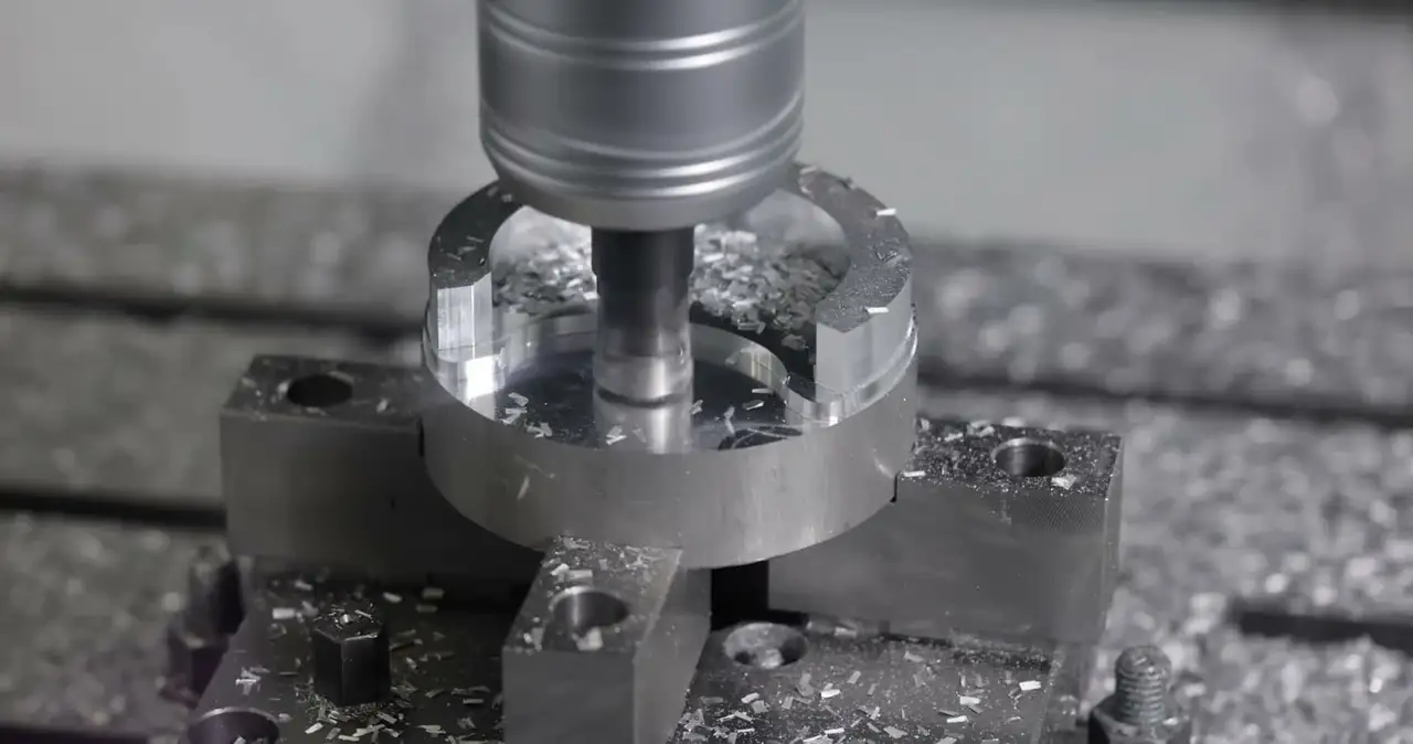
Start with your CAD file
Upload. Configure. Get your price.
STEP or STP
Encrypted · Max. 50 MB
The process
What is CNC milling?
CNC milling is a subtractive manufacturing process that shapes a solid block of material with rotating cutting tools. Computer-controlled motion enables repeatable production of precise features.
A STEP model is converted into toolpaths in CAM software. The milling machine follows those paths to remove material and produce the specified geometry and surface finish.
The process works with metals, plastics, and other machinable materials. It is widely used for prototypes and production components across automotive, aerospace, medical, electronics, and industrial applications.
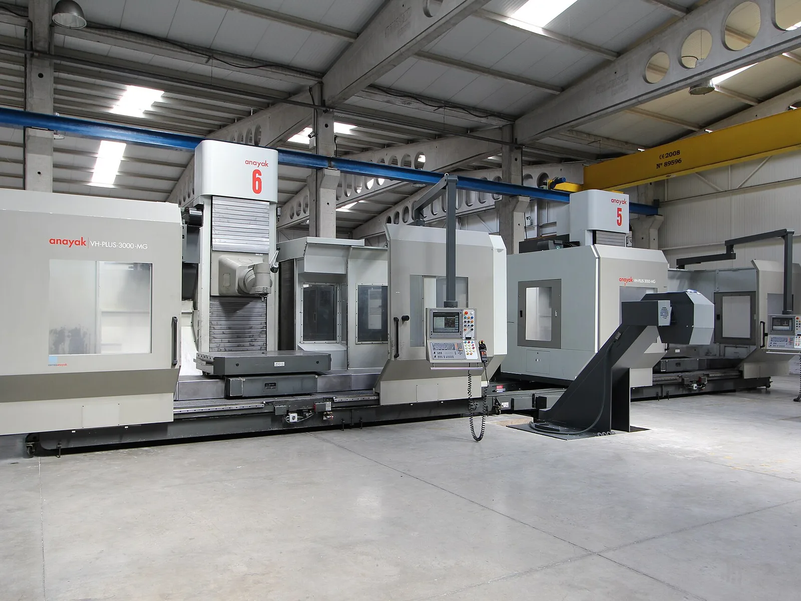
Controlled production
Capacity organized around repeatability.
Machine capability
The right axis strategy
for every geometry.
Axis count determines how much of a complex part can be reached in a single setup—affecting accuracy, surface finish, lead time, and cost.
 3Axis
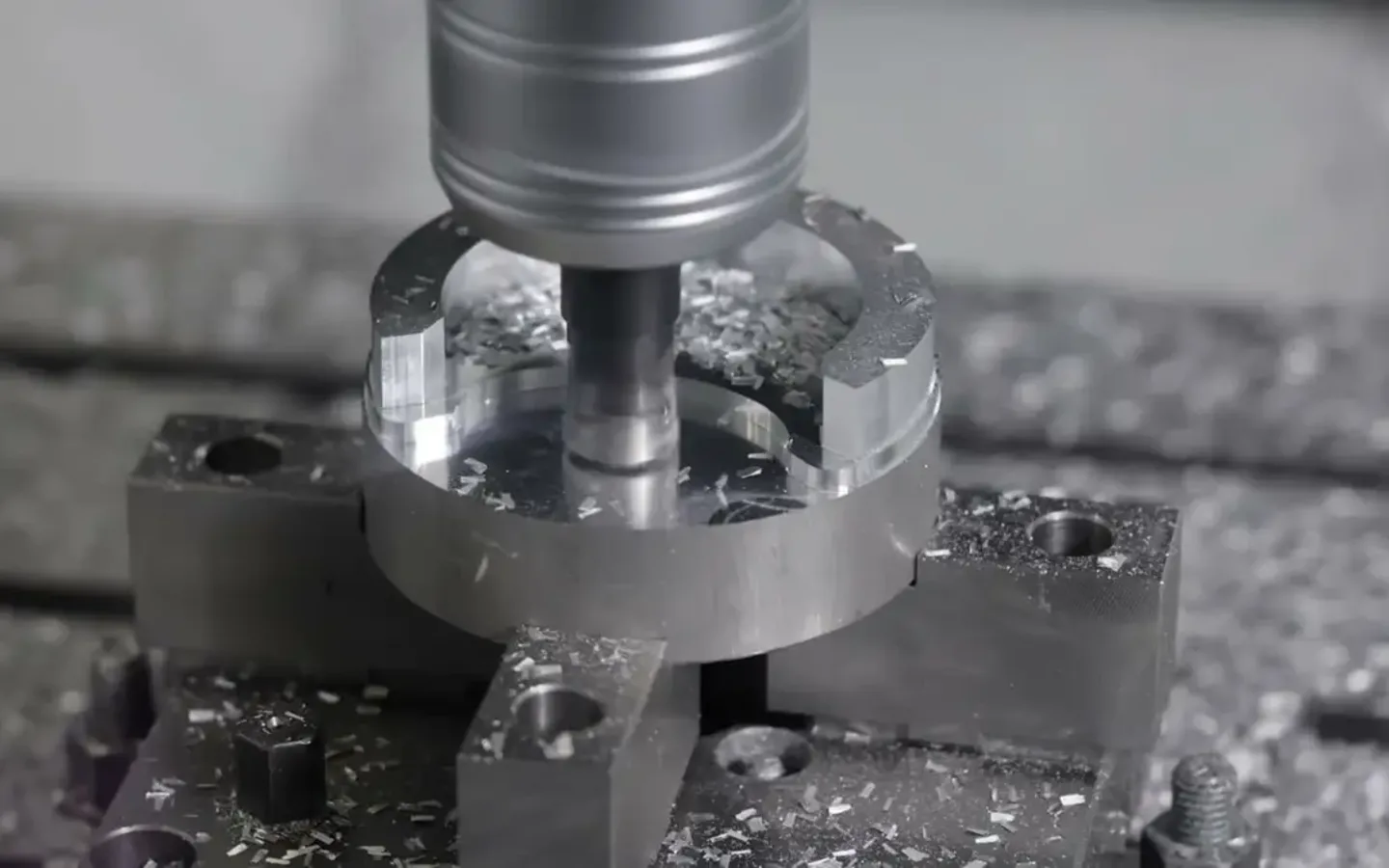
3-Axis CNC
X · Y · Z linear motion
The cutting tool moves along the X, Y, and Z axes while the part remains fixed. This is the standard configuration for planar surfaces, pockets, drilling, and contouring.
 4Axis
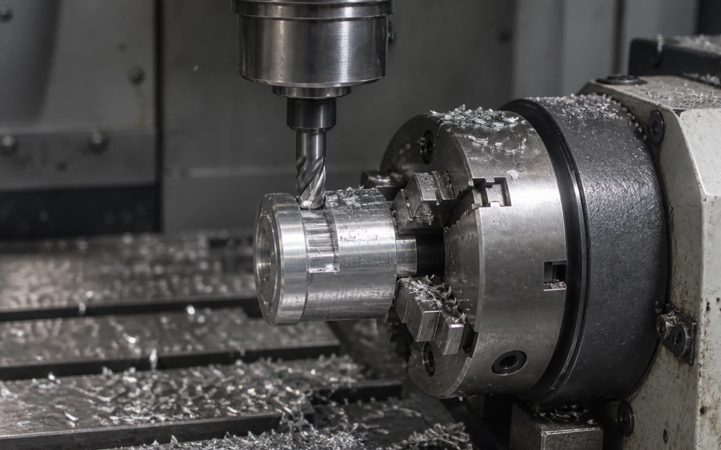
4-Axis CNC
X · Y · Z + A rotary axis
A rotary indexer turns the workpiece around its horizontal A axis while the spindle performs X, Y, and Z cutting moves. This enables machining around cylindrical parts and across multiple faces with fewer setups.
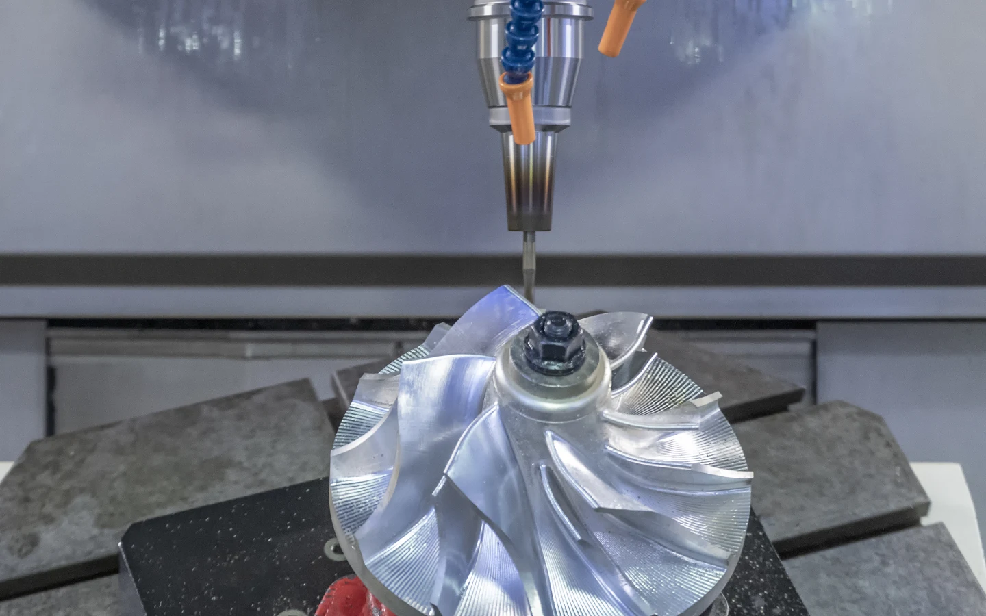 5Axis
5-Axis CNC
X · Y · Z + A + C rotary axes
Five-axis machining combines three linear axes with two rotary movements to reach complex surfaces and reduce repositioning.
What we machine
CNC milling operations.
From clean datum surfaces to complex freeform geometry, each operation is selected around part function and repeatability.
Face Milling
Creates a flat, smooth reference surface on raw stock.
Pocket Milling
Machines closed or open pockets for housings, covers, and structural parts.
Contour Milling
Machines external profiles and curved surfaces for complex or organic geometries.
Drilling & Tapping
Produces precision holes and standard tapped features from M3 through M24.
T-Slots & Dowel Holes
Creates locating and fastening features for precision assemblies.
3D Surface Machining
Machines freeform curved surfaces used in molds, patterns, and ergonomic parts.
Production envelope
Capability without ambiguity.
Representative CNC milling capabilities. Final limits depend on geometry, material, and order requirements.
Material library
Engineering materials, ready to machine.
Design for machining
Better decisions before the spindle starts.
Use these guidelines to improve manufacturability and reduce unnecessary machining time and cost.
Review your design with a quoteAvoid Deep, Narrow Pockets
Pockets deeper than a 4:1 depth-to-width ratio can cause tool deflection and chatter. Keep pocket depth near three times the width when possible.
Add Radii to Internal Corners
Round cutting tools cannot create perfectly sharp internal corners. Use an internal radius at least half the tool diameter.
Avoid Unnecessarily Tight Tolerances
Apply tight tolerances only to functionally critical dimensions and use an appropriate general tolerance elsewhere.
Use Standard Hole Sizes
Standard drill and thread sizes can be produced with readily available tooling, reducing cost and setup time.
Avoid Very Thin Walls
Thin walls can bend or chatter during machining. As a starting point, maintain at least 1 mm for metals and 1.5 mm for plastics.
Define Datum Surfaces
Clearly identify datum and setup references on the technical drawing so dimensions are measured from the intended origin.
Frequently asked
questions
Review common questions about CNC Milling. Contact our team when your drawing, material, or inspection requirements need project-specific review.
Can’t find your answer? Send our team the project details and technical files for review.
→ support@partgo.usYour next part starts here
Start building
better parts.
From first prototype to repeat production, tell us what you're building. Our manufacturing team will help you plan the fastest path forward.