CNC tolerances, made practical.
Use this guide to choose sensible dimensional tolerances, fits, GD&T controls, and surface requirements before you request a quote.
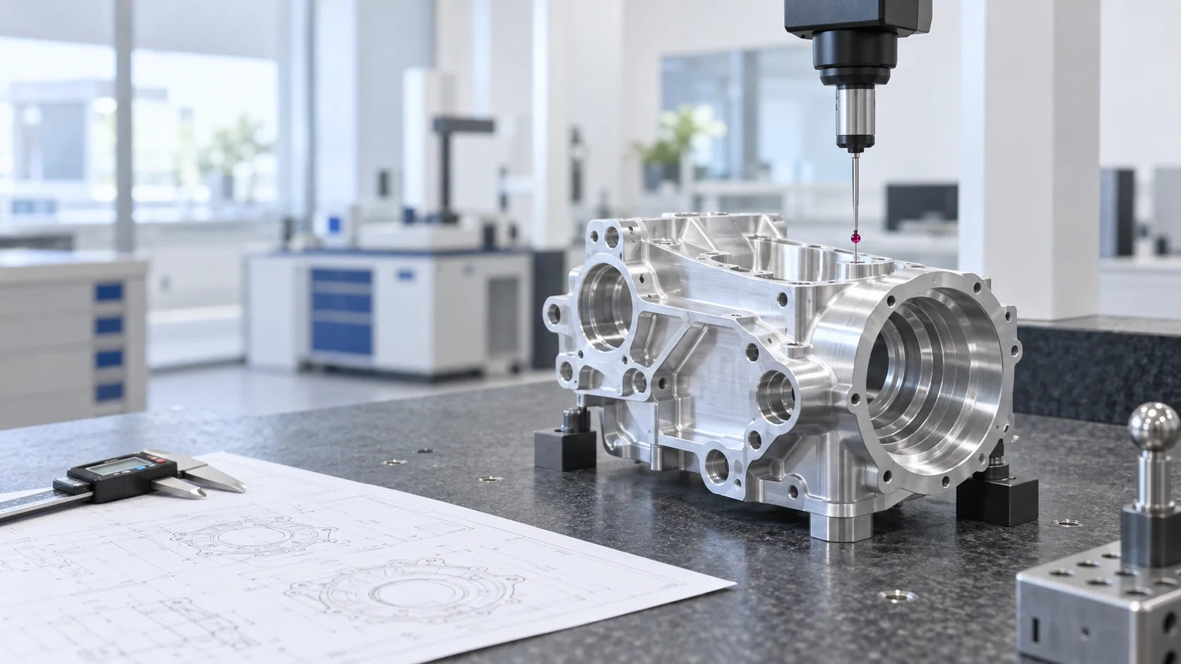
Tolerance follows function
Tighten only dimensions that control fit and performance.
01 / General tolerances
Start with the right tolerance class
ISO 2768 applies a general tolerance to dimensions that are not individually toleranced. Put the class in the drawing title block and call out critical features separately.
ISO 2768-m
Medium accuracy
A practical baseline for standard machined parts when no individual linear tolerance is shown on the drawing.
ISO 2768-f
Fine accuracy
For dimensions that need tighter control. It can affect setup, inspection, lead time, and manufacturing cost.
02 / Process capability
Choose precision in context
Capability changes with process, material, geometry, feature depth, setup, and inspection strategy. Treat these values as design guidance—not an automatic guarantee.
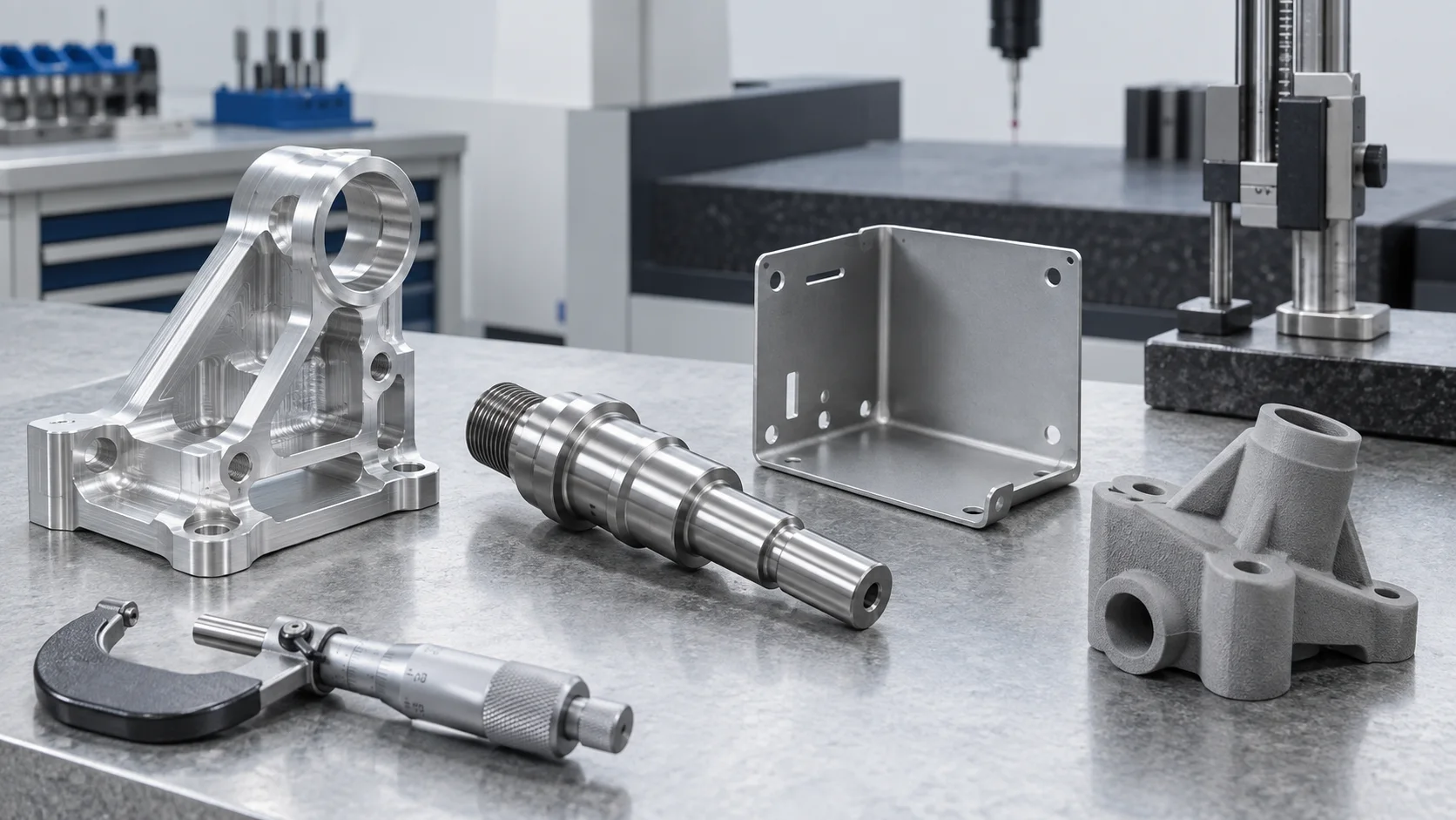
CNC Milling
Typical
±0.10 mm
Tight
±0.02 mm
- Min. hole Ø0.8 mm
- Metal wall from 0.5 mm
- Ra 0.8–3.2 µm
CNC Turning
Typical
±0.10 mm
Tight
±0.02 mm
- Min. diameter Ø1.0 mm
- Roundness from 0.01 mm
- Ra 0.8–3.2 µm
Sheet Metal
Typical
±0.20 mm
Tight
Project review
- Cut length ±0.50 mm
- Bend angle ±1°
- Thickness from 0.5 mm
3D Printing
Typical
±0.10–0.50 mm
Tight
Process dependent
- SLA typically ±0.10 mm
- SLS typically ±0.25 mm
- FDM typically ±0.50 mm
03 / GD&T
Control geometry—not just size
Geometric dimensioning and tolerancing defines how form, orientation, location, and runout relate to functional datums.
| Symbol | Control | Family | Typical value | Common application |
|---|---|---|---|---|
| ⏤ | Flatness | Form | 0.05–0.10 mm | Mating faces, cover flanges |
| ○ | Circularity | Form | 0.01–0.05 mm | Bearing seats, shaft diameters |
| ⌭ | Cylindricity | Form | 0.02–0.08 mm | Piston rods, precision bores |
| ∥ | Parallelism | Orientation | 0.05–0.20 mm | Guide rails, datum surfaces |
| ⊥ | Perpendicularity | Orientation | 0.05–0.15 mm | Hole axes, flange faces |
| ∠ | Angularity | Orientation | ±0.5°–±1° | Tapered or angled surfaces |
| ⊕ | Position | Location | Ø0.10–0.50 mm | Hole patterns, assembly features |
| ◎ | Concentricity | Location | 0.02–0.10 mm | Rotating components, shafts |
| ⌒ | Circular runout | Runout | 0.01–0.05 mm | Bearing journals, rotating shafts |
04 / ISO 286 fits
Design the assembly behavior
Use hole-and-shaft fit codes for bearings, pins, bushings, and other mating features. The selected fit controls whether the assembly slides, locates, or locks.
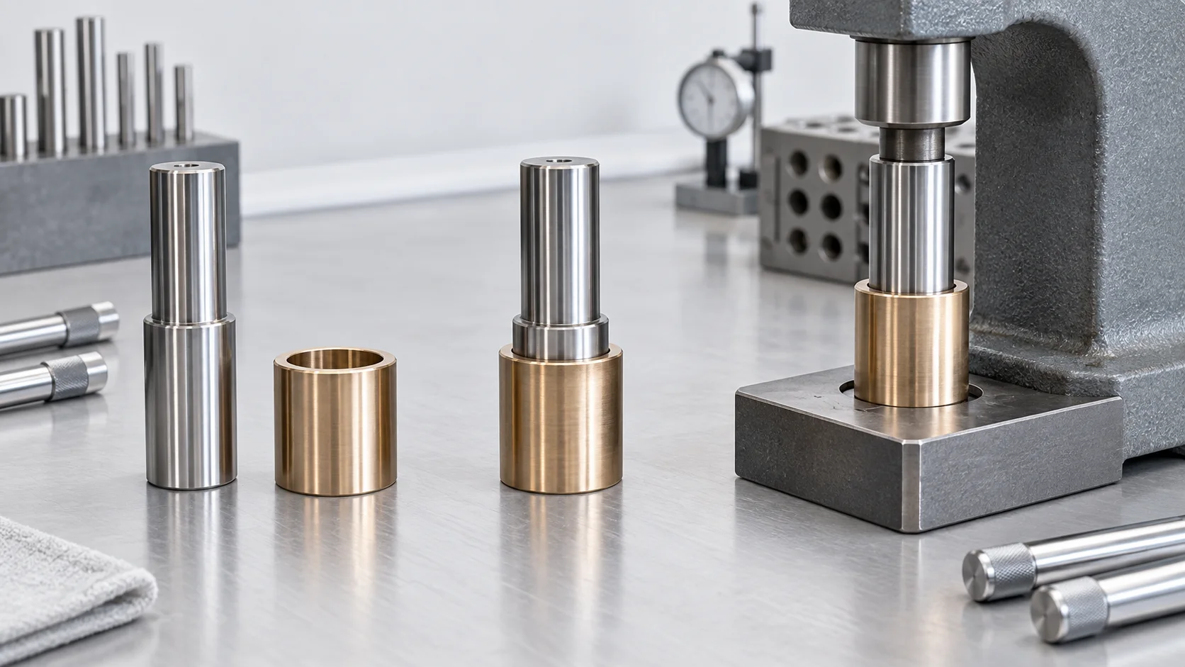
Clearance fit
Parts assemble by hand and retain controlled free movement.
Typical use: Guide shafts, sliding joints, serviceable assemblies
Transition fit
The tolerance stack creates either slight clearance or slight interference.
Typical use: Bearing races, locating hubs, dowel pins
Interference fit
The shaft remains larger than the hole and needs a press or thermal assembly method.
Typical use: Gear-to-shaft joints, fixed bushings, permanent pins
05 / Surface roughness
Specify the finish the function needs
A lower Ra value means a smoother surface—but also more process control. Consider friction, sealing, wear, cleaning, coating, and appearance.
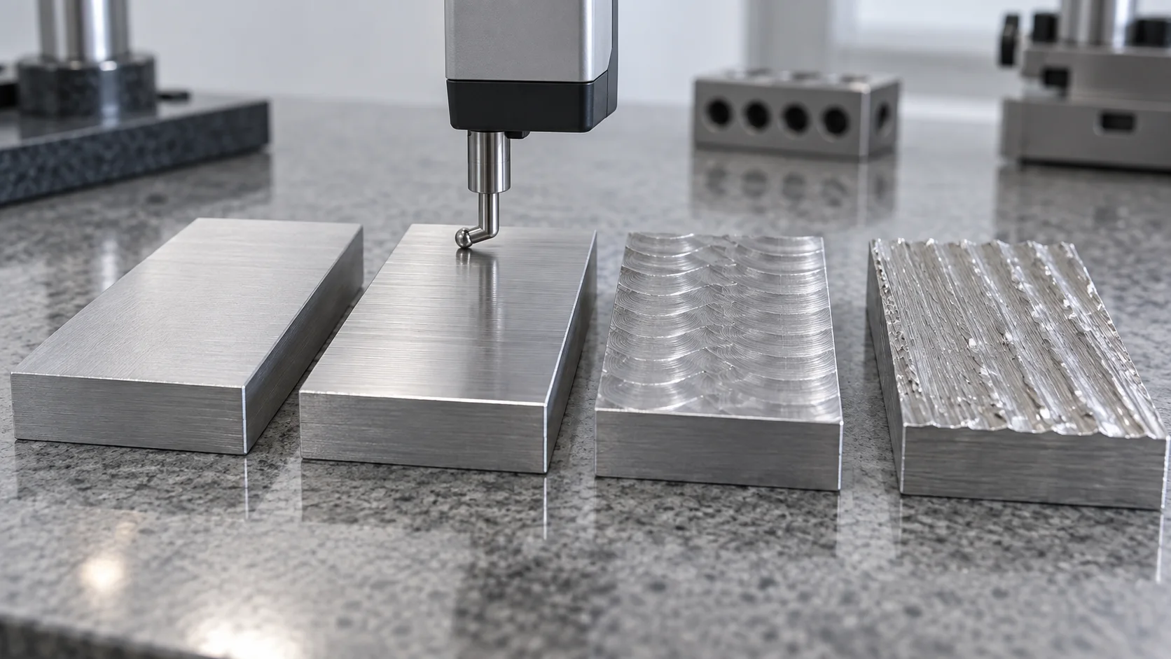
Ra 0.4
µm average
Grinding / honing
Bearing seats, hydraulic bores, precision sealing
Ra 0.8
µm average
Fine CNC machining
Shaft contacts, accurate mating and sealing faces
Ra 1.6
µm average
Standard CNC
CommonGeneral machine parts and assembly surfaces
Ra 3.2
µm average
Rough CNC / fabrication
Hidden, structural, or non-critical surfaces
06 / Drawing checklist
Make the drawing production-ready
A clear technical drawing reduces assumptions, avoids unnecessary cost, and gives the inspection team an unambiguous acceptance plan.
Define critical dimensions
Apply tight tolerances only where fit, motion, sealing, alignment, or performance requires them.
Show datums and GD&T
Use feature-control frames when form, orientation, location, or runout matters to the assembly.
Specify surface requirements
Identify functional surfaces, the required Ra value, and whether it applies before or after finishing.
State inspection needs
Call out critical-to-quality dimensions and any required inspection report or measurement method.
Include both the 3D model and 2D drawing
Upload a STEP/STP model for geometry and a PDF drawing for datums, critical dimensions, tolerances, threads, surface finish, heat treatment, and inspection requirements.
Engineering review
Not sure which tolerances your part needs?
Send the STEP file and drawing. PartGo can review critical features and confirm a manufacturable inspection approach for your project.