Sheet Metal · Cut, Bend & Join
Flat Stock.Finished Assemblies.
Custom sheet metal parts produced through laser cutting, precision bending, welding, and finishing—coordinated as one manufacturing workflow.
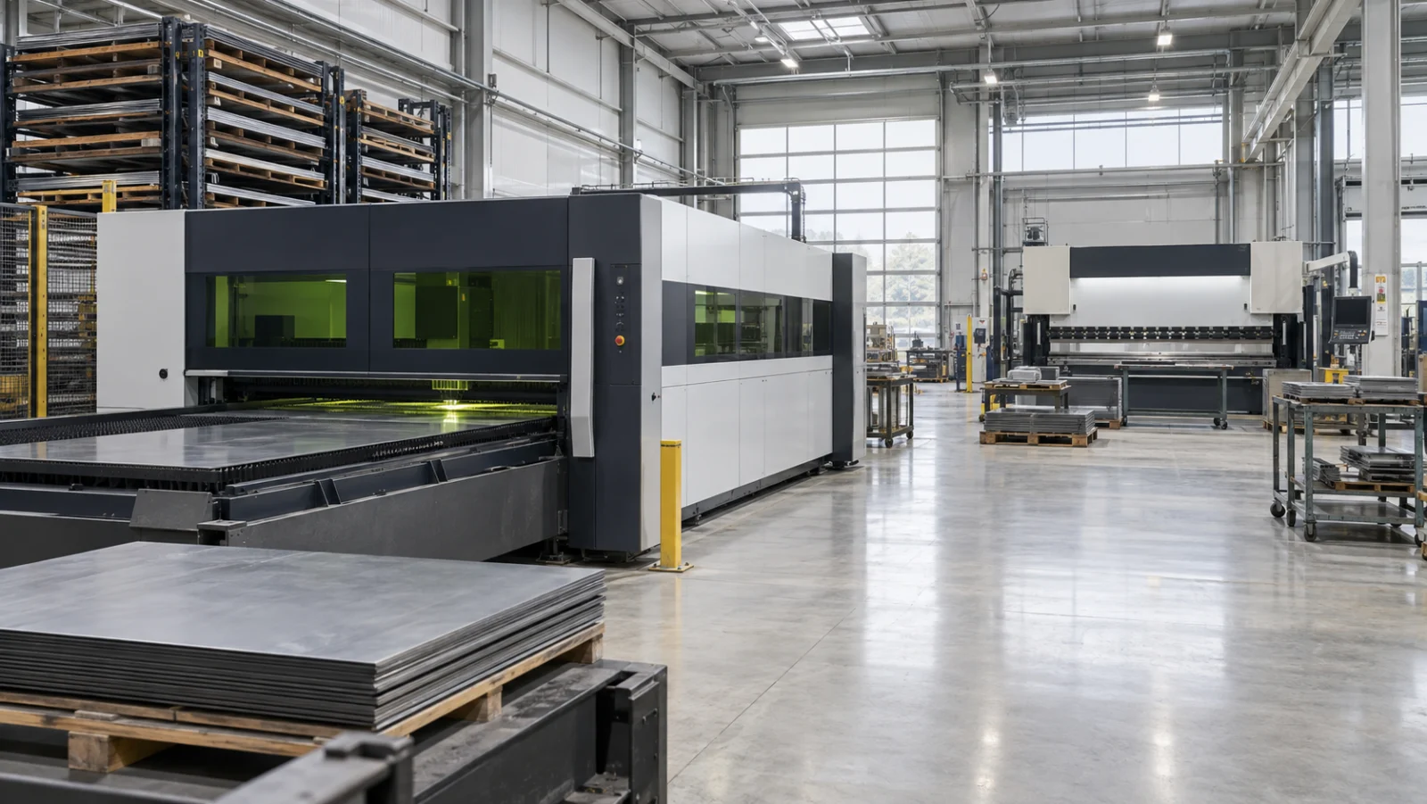
Start with your CAD file
Upload. Configure. Get your price.
DXF, DWG or STEP
Online quoting coming soon
What Is Sheet Metal Fabrication?
Sheet metal fabrication turns flat metal stock into three-dimensional parts through cutting, forming, and joining. Unlike CNC milling, the material is primarily cut, bent, and welded.
It is often an efficient choice for parts with large faces and relatively thin walls. Common applications include enclosures, panels, brackets, covers, frames, and equipment housings.
PartGo coordinates the required operations through one order workflow, from cutting and bending to welding, finishing, inspection, and delivery.
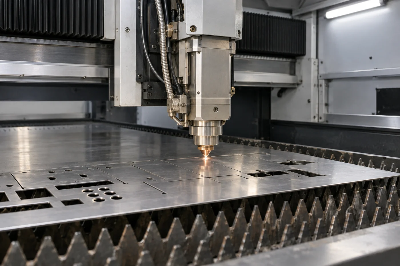
How Sheet Metal Parts Are Made
A typical workflow moves from the uploaded design through cutting, forming, joining, finishing, and inspection.
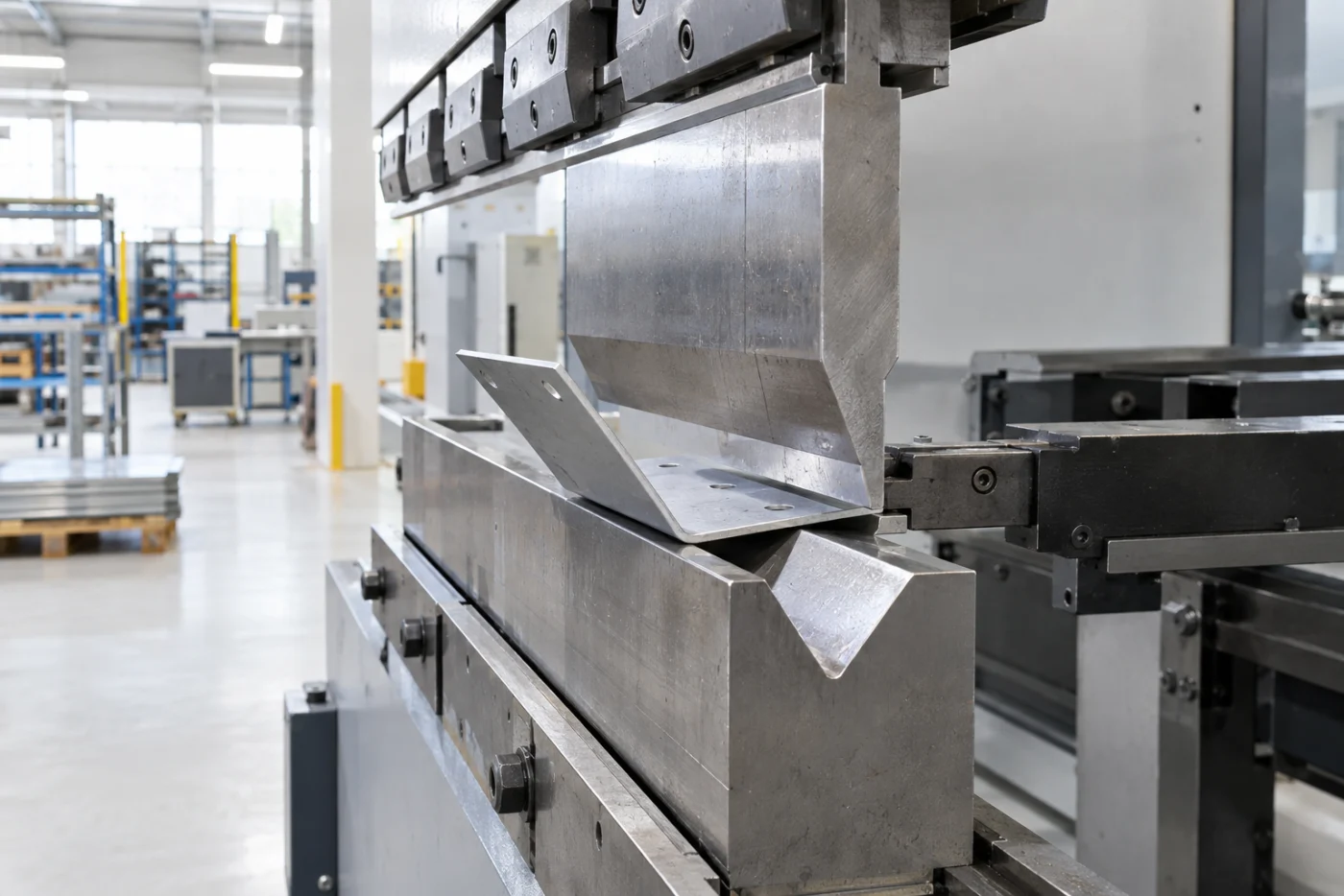
Laser Cutting
The DXF or STEP profile is cut from sheet stock, creating holes, slots, and the external contour.
CNC Bending
The flat blank is formed to programmed angles on a CNC press brake.
Welding & Assembly
Multiple components are joined using MIG, TIG, or spot welding as required.
Surface Finishing
Parts may be supplied as fabricated or receive a specified coating before inspection and delivery.
Sheet Metal Operations
Sheet metal fabrication combines multiple processes, from laser cutting through welding and assembly.
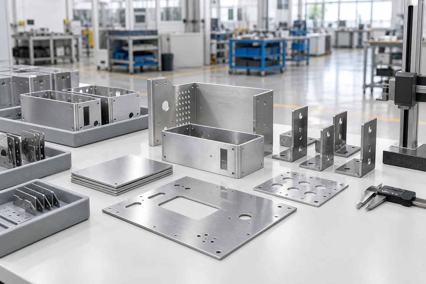
A CNC-controlled laser cuts profiles, holes, slots, and detailed contours from sheet stock without dedicated hard tooling.
A CNC press brake forms sheet stock to programmed angles and depths. Multiple bend sequences can create complex cross sections.
Laser-cut and formed components can be joined by TIG, MIG, or spot welding based on material, thickness, appearance, and structural requirements.
Secondary operations support precision holes, tapped threads, countersinks, punched features, and installed hardware.
Sheet Metal Capabilities and Tolerances
Representative capabilities are shown below. Final limits depend on material, geometry, and order requirements.
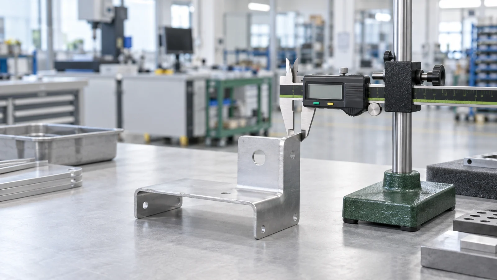
Sheet Metal Tolerance Guide
Achievable tolerance varies by operation. Use these values as general design guidance.
| Operation | Tolerance | Description | Rating |
|---|---|---|---|
| Laser cutting — profile | ±0.20 mm | External contours and profile dimensions | Standard |
| Laser cutting — length | ±0.50 mm | Overall panel length and width | Standard |
| Laser-cut hole diameter | ±0.10 mm | Minimum diameter depends on sheet thickness | Good |
| Bending — angle | ± 1° | Nominal value with springback compensation | Standard |
| Bending — length | ±0.50 mm | Dimensions measured from the bend line | Standard |
| Drilled-hole position | ±0.10 mm | Hole center relative to a datum | Precision |
| Welded assembly position | ±0.50 mm | Assembly tolerance across components | General |
Sheet Metal Design Tips
Use these guidelines to improve manufacturability and reduce avoidable fabrication cost.
Do Not Place Holes Too Close to a Bend
Keep hole edges far enough from the bend line to prevent distortion during forming. A common starting point is two sheet thicknesses plus the bend radius.
Account for Bend Allowance
Forming stretches the sheet through the bend region. Use the correct K-factor and bend allowance when developing the flat pattern.
Do Not Block Weld Access
Welding requires physical access for the torch, filler, fixturing, and inspection. Clearly identify any required internal welds.
Use an Appropriate Minimum Bend Radius
The minimum inside bend radius depends on material, temper, grain direction, and thickness. Radii that are too small can cause cracking.
Avoid Deep Forms in Very Thin Sheet
Deep channels and many consecutive bends can reduce stability in thin stock. Simplify the geometry or consider a thicker gauge.
Add Corner and Bend Reliefs
Reliefs where bend lines intersect help prevent tearing and improve corner quality during forming.
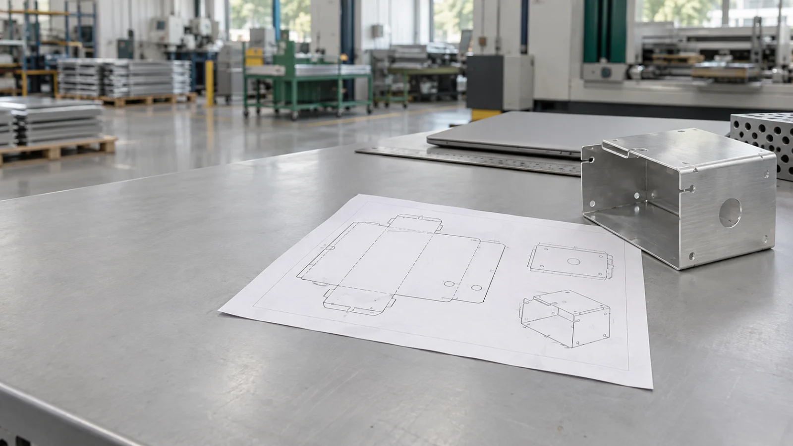
File Formats for Sheet Metal Parts
For best results, provide both the formed 3D model and the flat cutting profile when available.
DXF / DWGRecommended
DXF is the most direct format for a laser-cut flat pattern and clearly defines the cutting profile.
STEP / IGES
STEP is recommended for the formed 3D model because it communicates bends, final geometry, and assembly relationships.
Best File Combination
Submit STEP (formed 3D model) + DXF (flat pattern) together. STEP defines the final shape while DXF defines the cutting profile.
Frequently asked
questions
Review common questions about Sheet Metal. Contact our team when your drawing, material, or inspection requirements need project-specific review.
Can’t find your answer? Send our team the project details and technical files for review.
→ support@partgo.usSheet Metal Fabrication
Coming Soon
This service will be available soon. Leave your email and we’ll notify you when it is ready.
Your next part starts here
Start building
better parts.
From first prototype to repeat production, tell us what you're building. Our manufacturing team will help you plan the fastest path forward.