Engineering takeaway
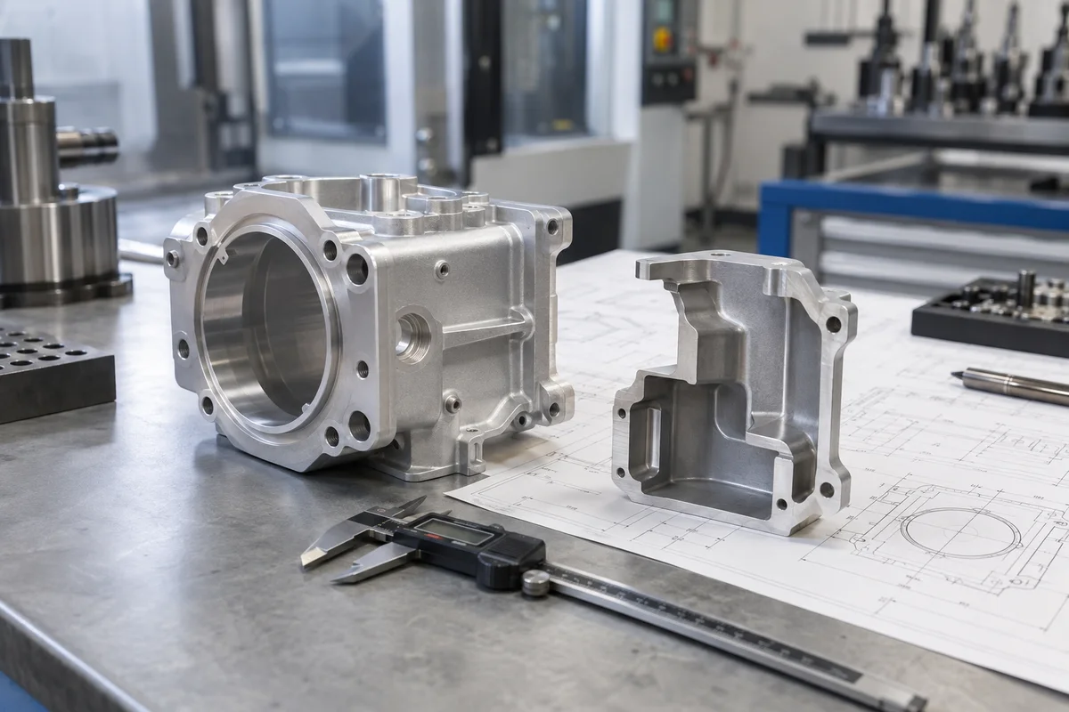
Treat the model, drawing, material specification, finish, and inspection plan as one production package. The best result comes from resolving tradeoffs before the part reaches the machine.
01
Define the finished geometry
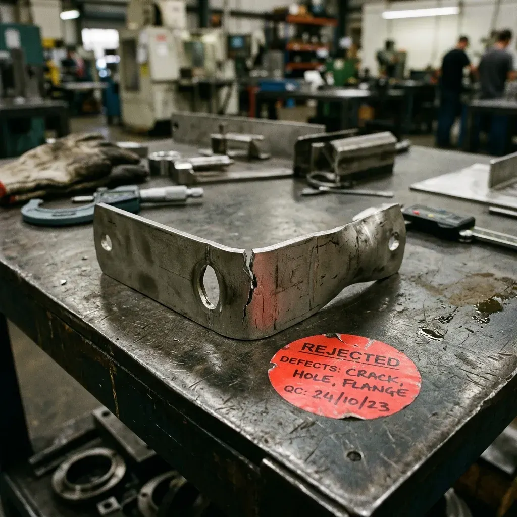
For Critical Sheet Metal DFM Mistakes, the formed part—not only the flat pattern—should drive the design review. Material thickness, bend direction, inside radius, flange length, and hardware locations all interact.
02
Respect forming constraints
Keep holes and cutouts away from bend zones, avoid unnecessarily short flanges, and use consistent radii where possible. These choices reduce distortion and simplify tooling.
- Functional interfaces identified
- Critical dimensions prioritized
- Material and finish specified
- Inspection needs documented
03
Coordinate joining and finishing
Welds, inserts, grinding, powder coating, plating, and masking affect both sequence and tolerance. Call out cosmetic faces and critical threads so they remain protected.
04
Send complete fabrication data
Provide a STEP model and drawing with material, thickness, bend notes, tolerances, grain requirements, hardware, weld symbols, finish, and inspection expectations.
Manufacture with clarity
Ready for an engineering review?
Upload your CAD file and share the material, quantity, finish, and critical requirements. Our team will review the actual project data before production.
Get an Instant Quote